Radio Occultation Principles
Note: This section is adapted from the GPS/MET introduction, found at
http://www.cosmic.ucar.edu/gpsmet/over/septsumm_top.html.
It is a bit dated
but still contains a useful introduction.
For CDAAC specific information, please
see below.
The radio occultation technique was first developed at the Stanford University
Center for Radar Astronomy (SUCRA) for studies of planetary atmospheres. Radio
occultation experiments at the Jet Propulsion Laboratory (JPL) have played a
prominent role in the NASA program for solar system exploration for more than
two decades. They have contributed uniquely to studies of the atmospheres of
Venus, Mars, the gas giants Jupiter, Saturn,
Uranus, and Neptune, as well as the
outer-planet satellites Io, Titan, and Triton. Typically, experiments involved a
spacecraft transmitter linked to a terrestrial receiver via a cm-wavelength
radio signal. The spacecraft trajectory was selected so that the propagation
path from the spacecraft to Earth passed through the planetary atmosphere under
study, producing distinctive variations in the amplitude and frequency (or
phase) of the received signal.
Fundamentally, the technique relies on the simple fact that a planet's
atmosphere acts much like a spherical lens, bending and slowing the propagation
of microwave signals passing through it tangent to the surface. The lens
effect results from decreasing atmospheric density with altitude. If the
positions of transmitting and receiving satellites are precisely known, the
"atmosphere delay" can be measured precisely, the time derivative of which
(Doppler) can be inverted to give atmospheric density vs. altitude.
For an Earth observing system based on the radio occultation technique, the
cost of maintaining a constellation of Earth orbiting satellites transmitting
on appropriate frequencies would be dominant. In contrast, the receiving
satellites would be relatively inexpensive. It so happens that the GPS exists,
is free of charge, and already has 24 satellites transmitting on frequencies
suitable for occultation observations. Moreover, by using the GPS to derive
the precise satellite positions, overall system complexity (and cost) are
further reduced. Thus, there is a strong economic incentive to base an Earth
radio occultation observing system on GPS.
The GPS is a state of the art satellite navigation system. It consists of 24
operational satellites, 4 in each of six 12 hour, 20,000 km circular orbits,
all inclined 55deg.. The resulting constellation produces global coverage 24
hours a day. There is no charge for use of the service and the U S Government
has recently issued a policy statement assuring the international community
that no user fees will be imposed for at least the next 10 years.
The GPS satellites transmit on two L-band carrier frequencies: 1575.42 MHz (L1)
and 1227.6 MHz (L2). Each carrier is phase modulated by a precise ranging code
(P code) consisting of pseudo random bit sequences at 10.23 Mb/s. In
addition, the L1 carrier is modulated in quadrature with a 1.023 Mb/s pseudo
random bit sequence used for the coarse (or clear) acquisition code (C/A code).
The transmit time, as kept by the clock onboard each GPS satellite, is
precisely known for each bit in the sequence. A GPS receiver identifies the
incoming code bits and measures their arrival time, as kept by the receiver
clock, with a precision of better than 1% of a bit length (about 1 nsec or 30
cm for the P code). A priori GPS orbital positions and clock offsets between
GPS satellites are broadcast to the user along with other information on a 50
bps data message superimposed on the L1 and L2 carriers. The difference
between the known transmit time and observed arrival time is a measure of the
distance between the satellite and receiver, plus the clock offset between
transmitter and receiver clocks, a quantity referred to as "pseudorange." A
receiver simultaneously measuring pseudorange to four satellites can
instantaneously determine its three components of position and its time offset
from GPS time, typically with an accuracy of 10-15 m and <1 microsecond
respectively. Modern receivers can also measure and keep continuous count of
carrier phase with a precision of better than .5% of a wavelength (~ 1 mm).
Continuous phase can then be used to construct a record of position
change with millimeter precision.
For reasons of national security, current U S Government policy calls for
limiting access to the Precision Positioning Service (PPS), and the accuracy of
the Standard Positioning Service (SPS). The technique used to limit the
access and the accuracy of GPS is called Anti
Spoofing (A/S). A/S is a process used to deny users access to
the full capabilities of the system by encryption of the high rate P code
normally required for high precision measurements. When so encrypted, the high
rate code is referred to as the "Y code". Unless the user has the required
"encryption key" to track the Y code, the user will not have access to the PPS.
For radio occultation, access to the highest precision available from GPS is required.
However, "Y Code receivers" and encryption keys are not needed. Instead, a
"codeless receiver", capable of tracking the L2 carrier phase without explicit
knowledge of the Y Code, is used.
Therefore, A/S does not impose any insurmountable limitation on the use of the GPS
for occultation measurements.
In GPS precision geodesy, "Double Differencing" (DD) is employed to effectively
cancel nearly all errors resulting from transmitter clock uncertainty and
receiver clock biases. As illustrated in Figure 2 below, the DD
technique starts by forming a "DD observable" from the linear combination of 4
observables, each with certain common errors. By differencing observations of
a given GPS satellite at 2 receivers, clock errors and S/A
dithering for that satellite are canceled. This is referred to as a
Single Difference (SD). If SDs are formed for a second GPS satellite and
differenced with the first SD, a DD is formed canceling errors common to the
receiver clocks. For COSMIC, a network of ground based receivers, located at
precisely known fiducial sites, will be used in conjunction with the data
collected from the COSMIC LEO receiver to implement the DD technique.
Figure
2 Double Differencing Geometry
The process described below might be considered the "classical retrieval
method". The fundamental principles have evolved over time from the original
planetary occultation work conducted at SUCRA and JPL, as described above.
Retrieval methods are improving all the time, however, and the COSMIC team is
investigating new techniques. The description of the retrieval methodology
which follows was first described in a paper on the GPS occultation technique
co-authored by scientists at Lockheed, SUCRA, and JPL.
To extract information on the neutral atmosphere, propagation delays caused by
the ionosphere must be isolated and removed from the signal. Electrons in the
ionosphere cause a frequency dependent delay in the phase of received
GPS signals. Anticipating the need for ionospheric corrections, GPS planners
designed into the system the use of two carrier frequencies, L1 and L2, as
previously described. By using dual frequency phase measurements, and
knowledge of the inverse square relationship between the group delay and the
frequency of each carrier, a simple linear correction can be derived.
This correction can be expressed as follows:
TDL1 = 1.5336 *  T (1) T (1)
where TDL1 is the
ionospheric delay on L1 and T is the measurable difference in
delay between L1 and L2. The Doppler frequency offset, also affected by the
ionosphere, can be modeled with a similar linear correction:
fL1 = 3.529 * ( fL2 - fL1)
(2) fL2 - fL1)
(2)
where (fL2 - fL1) is the measurable
Doppler difference.
Correcting for these ionospheric effects completes the first step in the
recovery of meteorological data from the observables.
The method described above provides a simple first order correction for
ionospheric effects. In most ground based applications, where the L1 and L2
rays follow substantially identical paths, it is sufficient. And for COSMIC,
it will provide sufficient accuracy for soundings below 30 km. However, for
profiles above 30 km, a more sophisticated ionospheric correction scheme is
required. To meet the requirement, an advanced technique which takes into
account the separation of the L1 and L2 rays has been developed by the
COSMIC team.
The fundamental measurement in the radio occultation technique is the time
delay of the signal, or resulting phase shift in the signal received from the
GPS transmitter. The radio signal
propagating from the GPS transmitter to the LEO receiver follows a path through
the atmosphere that curves distinctively in response to atmospheric gradients
in refractive index. The cumulative effect of the atmosphere on the ray path
can be expressed in terms of the total refractive bending angle,
 , as shown in Figure 3 below. , as shown in Figure 3 below.
The variation of with experiment geometry can be characterized
through use of an "impact parameter", a, defined as the perpendicular
distance between the center of the planet and the straight line followed by the
ray approaching the atmosphere. When combined with a precise knowledge of the
geometry (obtained concurrently from other GPS satellites), each sample of
phase data (corrected for ionospheric effects) can be converted to the
corresponding values for and a. This step is
straightforward and involves simple geometrical considerations, basic laws of
geometrical optics, and relativistic formulas for Doppler shifts.
For an atmosphere with local spherical symmetry (i.e., no significant
asymmetric horizontal variations in temperature or moisture), there is
a unique relationship between (a) and µ(r), the
atmospheric refractive index as a function of radius (r). The
refractive index profile µ(r) is then derived through an Abel transform
of the measurements of (a) obtained over the complete
occultation, as given in Eq. (3).
 (3) (3)
Here µ(rm) is the index of refraction of the layer a distance rm
from the center of mass of the planet, and am is the value of
a for the ray whose radius of closest approach is rm.
Application of Eq. (3) layer by layer, starting with the uppermost
atmospheric layer and working downward, will provide the index of refraction
profile through the atmosphere. This transformation has inherent in it the
assumptions that: (1) the atmospheric shells are spherical, and (2) each shell
has a uniform index of refraction, i.e., no horizontal variations.
The assumption of spherical symmetry, required for the classical retrieval
method, is a limitation which may need to be overcome to achieve the generality
desired for an operational system. However, the error introduced by using the
assumption of spherical symmetry may not be the dominant error source,
and therefor may be acceptable for operational systems. A recent paper by
Russian scientists Sokolovskiy and Gorbonov tend to support this possibility.
It should be noted that some
state-of-the-art ray tracing algorithms developed for seismology do not depend
on the assumption of spherical symmetry. We plan to explore the incorporation
of these advanced algorithms in our refractivity retrieval approach.
Classical atmospheric parameters of interest can be derived from the refractive
index profile through the following sequence of steps. To simplify the
explanation, the process will first be described for the case of dry air.
Then, the effect of moisture will be considered.
First, as the index of refraction, µ, is close to unity in the
terrestrial atmosphere, it is convenient to define the refractivity
N:
N = (µ-1) * 106
(4)
For
dry air, N can be expressed as:
N = 77.60 * (P/T)
(5)
where P is the pressure in millibars and T is the
temperature in Kelvins. Furthermore, the equation of state for dry air takes
the form:
 = 0.3484 * (P/T)
(6) = 0.3484 * (P/T)
(6)
where
is the air density in kg m-3. Equations (5) and (6)
show that is directly proportional to N for dry air, so
that (r) can be obtained easily from µ(r). Next, P(r)
can be obtained from (r) by integrating the equation of
hydrostatic equilibrium:
dP/dh = -g
(7)
where h is the height and g is the acceleration of
gravity. Finally, T can be obtained from P and
using Eq. (6). In summary, vertical profiles of , P, and
T can be obtained from µ(r) in a direct and simple manner.
The total refractive bending angle, , shown in
Figure 3 is greatly exaggerated. For the Earth's atmosphere, the
maximum bending angle is on the order of 0.02 radians ( 1deg. ). To place this
in perspective, the phase shift measurements made with the Voyager spacecraft
demonstrated that could be measured with an accuracy
approaching 10-8 radians. With comparable performance from a
space-borne GPS receiver, the refractive bending caused by the terrestrial
atmosphere could be resolved to about 1 ppm. It is this type of precision
in the radio measurements that leads to the expectation of obtaining high
precision vertical profiles of N, , P, and T
in regions of the atmosphere where the air is dry.
The procedure described above must be modified to account for the presence of
water vapor. When the effect of water vapor is included, the expression for
the refractivity becomes:
| N = | 77.60 * (P/T) |
+ | 3.730 * 105 * (Pw/T2) (8) |
| (DRY TERM) | | (WET TERM) |
where Pw is the vapor pressure of water in
millibars. The "dry term" from Eq. (5) has been supplemented by a contribution
from water vapor (the "wet term") which can be substantial in the lowest scale
height of the atmosphere above the Earth's surface. The moist term also
exhibits considerable variation with location and time. The separate
contributions to N by the dry and moist terms cannot be distinguished
uniquely through occultation measurements with the current capabilities of the
GPS satellites. This introduces
an ambiguity into the profiles of , P, and T; the
effects of water vapor at variable and uncertain concentrations are
indistinguishable from the effects of background variations in temperature and
pressure.
At altitudes above 8-10 km, this ambiguity is not a significant problem as the
contribution to the refractive index by water vapor is usually much less than
2%. Similarly, the contribution of moisture to refractive index is negligible
throughout the polar atmosphere during winter. In the lower troposphere, the
water vapor limitations can be overcome by one of several means, such as use of
auxiliary methods for estimation of water vapor content (e.g., through
microwave radiometry or ground-based GPS measurements) and use of independent temperature
measurements at known locations (e.g., radiosondes, aircraft). For example, if
the temperature profile in the troposphere was known from model calculations,
then moisture profiles could be retrieved from the measurements. This approach
will work best in tropical regions where the temperature profiles exhibit
relatively small changes, but moisture fields change significantly in space and
time. It should be emphasized that µ and N can still be
determined accurately regardless of the abundance of water vapor.
CDAAC Functional Overview
CDAAC will perform the following primary functions:
- Payload monitoring/control and ground fiducial net monitoring
- Incoming data quality checking
- Scientific data inversion
- Product validation
- Data distribution and archiving
Figure 1 illustrates the main functions of the CDAAC. Satellite
data are received from the COSMIC high latitude Earth stations, via
internet connections. This data stream consists primarily of
science data but also contains spacecraft and payload health and
status data. The CDAAC also receives data from the global fiducial
network of GPS and TBB receiver sites. The ground GPS data are
required to compute satellite orbits in a terrestrial reference frame
and to calibrate GPS receiver and transmitter oscillator
errors. Additional meteorological data, such as global model outputs
are required for the scientific data analysis - for water vapor
profiling and for validation of the results.
CDAAC expects to receive the fiducial data from the IGS and from
several sites deployed by UCAR to fill in gaps.
CDAAC will translate these data and
perform quality checking. Additional quality information
will be provided, based on results that will be obtained when using
the fiducial data. If problems are encountered the fiducial network
operations center(s) will be notified with requests for specific
action.
Figure 1 Schematic of CDAAC functions
By far most of the computing power and
development effort have been invested in the scientific data
analysis functions of CDAAC. Here the LEO data, the data from the
fiducial network, and additional meteorological data are combined
and inverted to obtain the COSMIC data products.
The CDAAC will generate results (products)
on average within 3 hours of data collection. Additional high accuracy
(post-processed) results will be computed for climate research and archive after the highest
accuracy post-processed satellite orbits are available from the
International GPS Service (IGS) within 4-6 weeks after data
collection.
CDAAC will distribute its data and products to a broad range of
scientific and operational users. Products will be made available on
the Internet and will be freely distributed.
The current data storage plan calls for use of the NCAR mass storage
system for COSMIC data. This archive will support researchers worldwide that
do not require real-time data for their work. Climate data, and data
for weather and space weather research, for example, will be accessed
through this archive.
CDAAC in the COSMIC context
In addition to the six LEO satellites the COSMIC system requires
significant ground infrastructure. The key components and
communications links of the COSMIC system are shown in Figure 2.
Each COSMIC satellite dumps its data to one of two high latitude
receive-only Earth stations once per orbit every 100 minutes for
immediate transmission to the near real-time CDAAC at UCAR. The CDAAC
also receives GPS data, from a global network of 40-50
ground based receiver sites in near real time (within ~10 min.). These
GPS fiducial data are needed to compute precise COSMIC satellite
orbits, and to eliminate errors due to GPS transmitter and receiver
clock oscillator instabilities.
The CDAAC analyzes all data and monitors payload performance. Data
and higher level products will be provided to researchers and operational
centers worldwide. All data and products will also be mirrored
at NSPO/CWB in Taiwan. NSPO will be responsible for mission operation and
control including all satellite uploads from the two Taiwanese ground
stations, and for the distribution of data and products to the
Taiwanese operational and science communities.
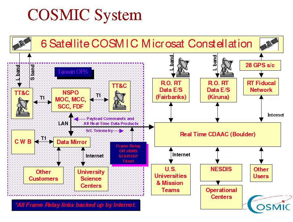
Figure 2 Satellite and ground segments of COSMIC
Data Processing and Delivery to Users
CDAAC will compute two solutions: A near-real-time
solution for weather forecasting and space weather monitoring
applications, and a more accurate
and better-validated post-processed solution for climate and
atmospheric research. One important goal of the CDAAC is
delivery of highest quality global data products within 3 hours to
the operational and science community, to demonstrate the value of
this data set to weather prediction and space weather
monitoring.
As soon as the data from a 100-minute orbit have been dumped at an
Earth station and forwarded to the CDAAC they are analyzed. About
20-40 minutes after data arrival, the analysis center will provide
several higher level products. Profiles of temperature, pressure,
humidity, refractivity, and refractive bending angles will be computed
for the neutral atmosphere. In
the ionosphere the CDAAC will compute profiles of electron density and TEC.
Profiling analysis will require COSMIC satellite
orbits to be computed precisely--these results will be made available with
other COSMIC data. Line of sight TEC measurements from all GPS COSMIC and
ground-to-space links will also be made available. Data from the TIP
and TBB instruments will also be processed. TIP data will be included in
the profiling inversion of the ionospheric
occultation data.
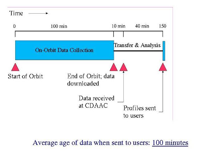
Figure 3 Time delay for COSMIC data products
Products shall be transmitted via Internet to researchers,
educators and operational users for assimilation into numerical
models, and they will be archived for further research and education
applications. The total archived data volume including raw data and
higher level products is expected to be ~ 3 Gbytes/day.
The data from the COSMIC scientific experiment and CDAAC products
will be made available to all interested parties in all countries,
free of charge or at the marginal cost of reproduction and
distribution.
|